English
 中文简体
中文简体
Understanding the Role of Current Transformers in Modern Electrical Systems
Current transformers (CTs) have become indispensable components in electrical systems, enabling safe and efficient energy monitoring. These devices step down high currents to measurable levels, providing critical data for power management. As industries shift toward smart grids and renewable energy integration, the demand for precise current measurement has never been higher. This article explores five key aspects of current transformer technology that are shaping the future of energy management.
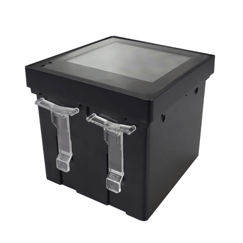
![]()
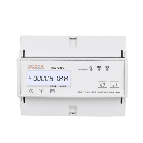
Ring One PCS Design Current Transformer
1.1 Current transformer accuracy class explained: Why Precision Matters
The accuracy class of a current transformer determines its measurement precision under specific conditions. Common classes include 0.1, 0.2, 0.5, and 1.0, with lower numbers indicating higher accuracy. For commercial metering, class 0.5 is typically required, while protective relaying might use class 1.0 or higher. The table below compares different accuracy classes:
| Accuracy Class | Typical Application | Error Margin |
|---|---|---|
| 0.1 | Laboratory standards | ±0.1% |
| 0.2 | Precision metering | ±0.2% |
| 0.5 | Commercial billing | ±0.5% |
| 1.0 | Protective systems | ±1.0% |
Understanding current transformer accuracy class explained helps engineers select the right device for their specific needs. Factors like burden, frequency, and temperature all affect accuracy. Modern digital systems often combine multiple accuracy classes to optimize both measurement and protection functions within the same installation.
1.2 The Impact of Core Materials on Performance
Different core materials significantly influence current transformer characteristics. Silicon steel offers good performance for power frequency applications, while nickel-iron alloys provide better accuracy for wider frequency ranges. Nanocrystalline cores represent the latest advancement, offering exceptional linearity and reduced core losses.
Innovative Applications of Current Transformer Technology
2.1 Split core current transformer installation guide for Retrofit Projects
Split-core CTs have revolutionized electrical monitoring in existing installations. Unlike traditional solid-core transformers, these devices can be installed without disconnecting conductors. Our comprehensive split core current transformer installation guide covers essential steps:
First, verify the conductor size matches the CT's rating. Second, ensure proper alignment to prevent measurement errors. Third, check that the closure mechanism securely locks the core. Fourth, maintain adequate clearance from other conductors. Finally, verify the secondary circuit burden doesn't exceed specifications.
Split-core CTs typically sacrifice some accuracy (usually class 0.5 to 1.0) for installation convenience. However, modern designs have narrowed this gap significantly, making them viable for many billing-grade applications where previously only solid-core units could be used.
2.2 How to test current transformer ratio: Field Verification Techniques
Regular testing ensures current transformers maintain specified performance. The primary method for verifying turns ratio involves injecting a known current and measuring the secondary output. Modern test sets can perform this automatically, but understanding how to test current transformer ratio manually remains valuable:
Using a variable current source, apply 10-20% of rated current to the primary. Measure primary and secondary currents simultaneously with calibrated instruments. The ratio should match the nameplate value within the accuracy class tolerance. Phase angle measurements are equally important for applications requiring precise power measurements.
| Test Method | Equipment Needed | Accuracy |
|---|---|---|
| Primary injection | Current source, meters | High |
| Secondary injection | Specialized test set | Very High |
| Voltage method | Voltage source, meters | Medium |
Advanced Concepts in Current Transformer Design
3.1 Rogowski coil vs current transformer: When to Use Each Technology
The debate between Rogowski coil vs current transformer centers on application requirements. Rogowski coils offer advantages like wide frequency response and no saturation risk, while traditional CTs provide better accuracy at power frequencies and don't require external power.
Key differences include: - Rogowski coils measure current derivatives (di/dt) requiring integration - Traditional CTs directly produce proportional current - Rogowski coils handle very high currents without saturation - CTs offer better low-current resolution
For most power system monitoring, traditional CTs remain preferred due to their simplicity and accuracy. However, Rogowski coils excel in applications like arc flash detection or variable frequency drives where traditional CTs might saturate or introduce phase errors.
3.2 Current transformer saturation calculation Methods
Understanding current transformer saturation calculation prevents measurement errors and protection system malfunctions. Saturation occurs when the core can't support additional magnetic flux, causing nonlinear output. The saturation voltage Vs can be calculated as:
Vs = 4.44 × f × N × Ac × Bmax
Where f is frequency, N is turns, Ac is core area, and Bmax is maximum flux density. Engineers must ensure the CT's saturation voltage exceeds the maximum expected secondary voltage (Isc × Rburden).
Emerging Trends in Current Measurement Technology
4.1 Digital Current Transformers: The Next Evolution
Digital CTs incorporate analog-to-digital conversion directly within the transducer, offering advantages like noise immunity and direct interface with digital protection relays. These devices often include advanced features like self-monitoring and communication capabilities.
4.2 Integration with IoT Energy Management Systems
Modern current transformers increasingly incorporate wireless connectivity and data logging capabilities. This enables real-time energy monitoring across distributed systems without extensive wiring infrastructure. The data from these systems feeds into advanced analytics platforms for predictive maintenance and optimization.
Practical Considerations for Current Transformer Selection
5.1 Environmental Factors Affecting Performance
Temperature, humidity, and vibration all impact current transformer reliability. Outdoor installations require weatherproof enclosures, while industrial environments might need additional shielding against electromagnetic interference.
5.2 Future-Proofing Your Current Measurement System
When designing new installations, consider potential future expansions. Selecting CTs with multiple ratio taps or digital interfaces can accommodate changing requirements without complete system replacement.