English
 中文简体
中文简体
Single-phase DIN rail electric meters are widely used in residential, commercial, and small industrial applications for accurate energy monitoring. Whether you're an electrician, engineer, or DIY enthusiast, understanding how to install, troubleshoot, and compare these meters with three-phase alternatives is essential.
1. Single Phase vs. Three Phase DIN Rail Meters: Key Differences & Applications
Single-phase and three-phase DIN rail meters serve different purposes depending on the electrical load requirements.
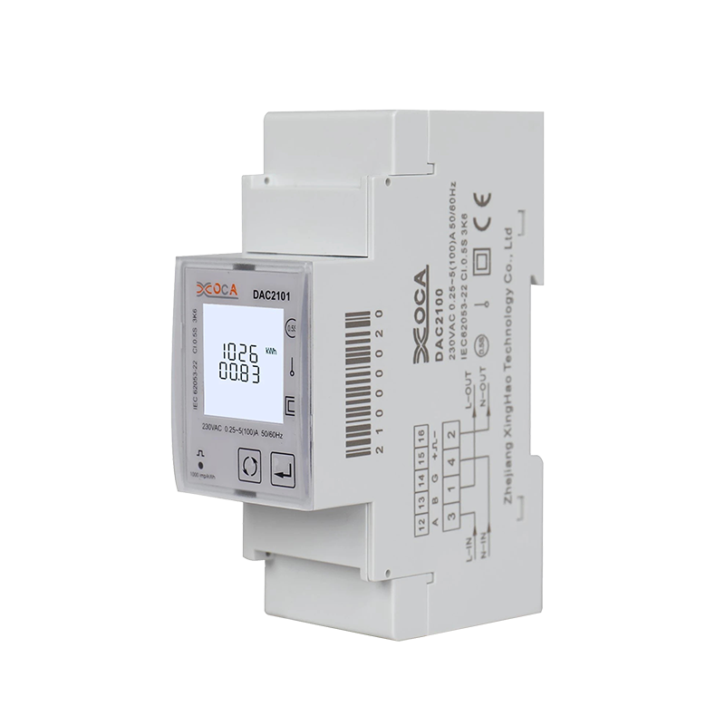
Single-Phase Meters
Used in residential and small commercial settings.
Operate on a 230V (or 120V, depending on region) supply.
Suitable for low to moderate power loads (e.g., homes, small shops).
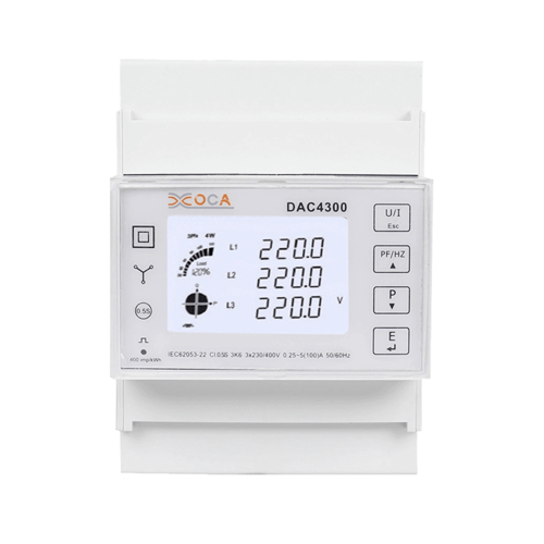
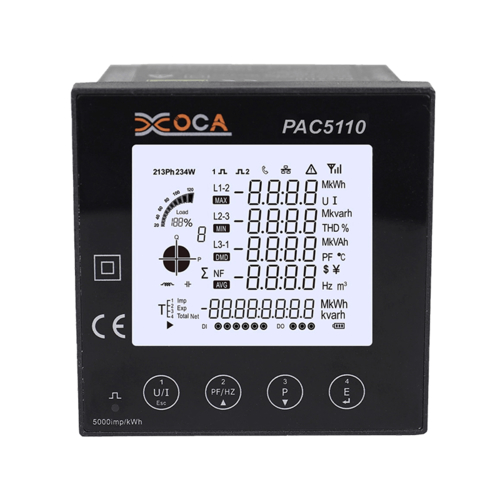
Three-Phase Meters
Designed for industrial and large commercial applications.
Operate on 400V (or 208V/480V in some regions).
Handle high-power equipment (e.g., motors, heavy machinery).
Key Differences
| Feature | Single-Phase Meter | Three-Phase Meter |
|---|---|---|
| Voltage | 120V/230V | 208V/400V/480V |
| Power Supply | 1 live wire + 1 neutral | 3 live wires + 1 neutral |
| Load Capacity | Up to ~10 kW | 10 kW to several MW |
| Applications | Homes, small offices | Factories, data centers |
| Installation Complexity | Simple | Requires balanced load management |
Which One Should You Choose?
For homes & small businesses → Single-phase is sufficient.
For factories, large buildings, or heavy machinery → Three-phase is necessary.
2. How to Install a Single Phase DIN Rail Electric Meter: Step-by-Step Guide
Safety Precautions Before Installation
Working with electrical components requires strict adherence to safety protocols to prevent accidents or equipment damage. Before beginning the installation process, ensure the main power supply is completely disconnected to avoid electric shock. Verify the absence of voltage using a reliable multimeter or voltage tester. Equip yourself with insulated tools and wear protective gear such as rubber gloves and safety goggles to minimize risks. Additionally, confirm that the working environment is dry and free from conductive materials that could cause short circuits.
Essential Tools and Materials
A successful installation requires the proper tools and components. You will need a standard DIN rail, typically 35mm in width, which serves as the mounting platform for the meter. A screwdriver set with insulated handles is necessary for securing connections, while wire strippers will help prepare the conductors. A digital multimeter is indispensable for verifying voltage and continuity, and a pair of pliers may be needed for bending and securing wires. Ensure you have appropriately sized cables that match the current rating of the meter, along with terminal blocks if additional wiring organization is required.
Detailed Installation Procedure
Step 1: Mounting the DIN Rail
The first step involves securely mounting the DIN rail inside the electrical distribution panel. Choose a location that allows easy access for wiring and future maintenance while ensuring sufficient clearance around the meter for heat dissipation. Use sturdy screws to attach the rail, checking with a level to confirm it is perfectly horizontal. A misaligned rail may cause improper seating of the meter or strain on the connections.
Step 2: Attaching the Electric Meter
Once the DIN rail is firmly in place, the single-phase meter can be installed. Most modern meters feature a snap-on mechanism that allows them to clip directly onto the rail. Align the meter with the rail and apply gentle pressure until you hear a distinct click, indicating secure attachment. If the meter includes locking tabs, ensure they are fully engaged to prevent accidental dislodging.
Step 3: Wiring Connections
Proper wiring is critical for accurate meter operation and safety. Begin by connecting the live (L) input terminal to the incoming phase wire from the power supply. The neutral (N) input must be linked to the corresponding neutral line, while the load-side terminals should be connected to the circuit being monitored. Double-check that all conductors are firmly secured under the terminal screws without any stray strands that could cause short circuits. For enhanced safety, consider using ferrules on stranded wires to prevent fraying.
Step 4: Power-Up and Verification
With all connections completed, carefully restore power to the system. Observe the meter's display for initialization, which should indicate voltage presence and correct polarity. Use the multimeter to confirm that the voltage readings at the meter terminals match the expected values. If the meter includes additional features like pulse outputs or communication interfaces, verify their functionality according to the manufacturer's guidelines.
Common Installation Mistakes and Prevention
Improper installation can lead to inaccurate readings or equipment failure. One frequent error is reversing the live and neutral connections, which may damage sensitive electronic components inside the meter. Another issue arises from loose terminal connections, causing intermittent readings or overheating over time. To prevent these problems, always follow the wiring diagram provided with the meter and perform a thorough inspection before energizing the system. Additionally, ensure the selected wire gauge can handle the expected current without excessive voltage drop.
3. Troubleshooting Common Issues with Single Phase DIN Rail Electric Meters
Identifying and Resolving Power-Related Problems
Meter Fails to Display or Register Consumption
When a meter shows no signs of activity, the first step is to verify the presence of supply voltage at the input terminals. Using a multimeter, check between the live and neutral connections to confirm proper voltage levels. If no voltage is detected, inspect upstream components such as circuit breakers or fuses that may have tripped or blown. Loose wiring connections are another common culprit, particularly in installations where vibration or thermal cycling occurs. Tighten all terminal screws and examine wire integrity, looking for signs of corrosion or physical damage that could interrupt conductivity.
Inconsistent or Inaccurate Energy Measurements
Erratic readings often stem from incorrect current transformer (CT) configurations or improper meter calibration. If the installation uses external CTs, ensure their ratio settings match the meter's specifications. Electrical no
ise from nearby high-power equipment can also distort measurements; installing ferrite cores around signal wires or relocating the meter away from interference sources may resolve this. For meters with programmable settings, a factory reset followed by reconfiguration might be necessary to restore accuracy.
Addressing Physical and Operational Faults
Overheating and Thermal Stress
Excessive heat generation in the meter or its connections usually indicates overloading or poor contact resistance. Begin by measuring the actual current flow compared to the meter's rated capacity. If loads exceed specifications, consider redistributing circuits or upgrading to a higher-rated meter. Inspect terminal blocks for signs of arcing or discoloration, which suggest loose connections generating resistance heat. Cleaning oxidation from contact surfaces and applying antioxidant compounds can improve long-term reliability.
Communication Failures in Smart Metering Systems
Advanced meters with remote monitoring capabilities may experience communication dropouts due to wiring issues or configuration errors. For RS-485 or Modbus networks, verify that all devices share a common ground and that cable shielding is properly terminated. Check the baud rate and parity settings against the host system's requirements, as mismatches will prevent data exchange. In wireless systems, signal strength tests can identify dead zones requiring repeater installation or antenna repositioning.
Proactive Maintenance Strategies
Preventing meter issues starts with regular inspections and testing. Schedule periodic checks of terminal tightness, especially in environments with significant temperature fluctuations that may cause metal expansion and contraction. Keep firmware updated for smart meters to ensure compatibility with evolving network protocols. Maintaining a log of historical performance data helps identify gradual degradation before it leads to failure. By adopting these practices, users can maximize meter lifespan and measurement reliability while minimizing unexpected downtime.